Wednesday, December 7, 2011

Star Wars Christmas Tree...Now with Sound

A few days ago I posted a set of Christmas tree lights that flashes to the Star Wars theme song.  I initially did not include a sound output intentionally because the tree sits in our dining room and it'd be annoying to have a song playing whenever we had the tree lit.  I decided later that as long as I could turn the sound off, it'd be a fun addition to the project, so I added a small piezo buzzer between pins 8 & 9 of the MSP430 and made the software changes necessary to output the song on the buzzer as well as on the lights.  I soldered a couple female headers onto my protoboard so that I can plug the buzzer in (to have sound) or take it out (for lights only).


In order to add the sound, I had to go back to the music and re-transcribe it with the actual note values (I ignored flats/sharps before because you couldn't really distinguish them on the lights...but it matters more with the sound).  I looked up the frequencies of those notes here.  The notes in the song range in frequency from ~294 Hz to 880 Hz.  I tried to keep the structure of my code as similar to the first version as possible, so the audio PWM is handled in software in the interrupt routine that fires when Timer A reaches the end of its period for the LED PWM.  I bumped up the DCO frequency from 1Mhz to 8Mhz to provide finer resolution for the musical notes, but the rest of the changes are pretty minor.  An updated version of the source code is available at https://sourceforge.net/projects/starwarsxmasled/.

Sunday, December 4, 2011

Star Wars Christmas Tree

In addition to all of the Christmas trees, ornaments, stockings, garlands, and other decorations that fill our house for the Christmas season, my wife lets me have one small tree of Star Wars Ornaments.  For the past few years it has been unlit, and she decided that it needed some lights this year.  She found a battery operated strand of 30 white LEDs on sale at Target last week, but I figured we could do better than just plain lights.....we needed Star Wars lights.  I built a small controller for the light strand that makes it flash in the pattern of the Star Wars theme song.  The basic concept is that the note durations are how long the lights are on, and the pitch translates to light intensity.  The lowest note in the song corresponds to the dimmest light setting, and the highest note to the brightest. 


I first cut the strand and measure that it draws ~70 mA with a new set of 4xAA batteries, which is way more than a mcu gpio can output, so I started with a 2n3904 transistor to turn the strand on and off.  I really only needed 1 pin from an mcu, so I went to my parts box and dug around for small microcontrollers.  The two options I had on hand were an AVR ATTINY85 and a handful of MSP430 microcontrollers.  I had a couple of ez430 thumbsticks that TI was giving away a while ago, along with a pack of the extra target boards, and this project was well suited to the small form factor and ease of use that those provide.  I ended up using one of the MSP430F2012 target boards.  It has a built in LED, which I did my initially firmware testing with to get  the note lengths and song pace working right, and then I used PWM output from the Timer A module to control the intensity of the LEDs on the actual strand.  

I'm not really a musical person, and all of the notes on the piano sheet music I was finding just confused me, so I found a violin arrangement (so only 1 note is being played at a time) and set about transcribing that into code for my microcontroller.  I broke the song down into repeating chunks so that I wouldn't have to code in every single note and could reuse the chunks.  Each note is represented by a single byte, where the lower three bits represent the length of the note, and the upper bits represent the pitch.  I went through and labeled the notes 1-12 from lowest to highest, and store those values, which are mapped to the range of PWM duty.  I recorded the note duration and pitch by hand for the whole song, and then used an Octave script to combine the values into my chosen representation of the information.


In the next picture you can see the circuit board a little closer.  I'm using an LM317 with a couple resistors and capacitors to provide 3.3V for the MSP430, and then the LED strand is switched on my a 2n3904 transistor with a 1k resistor on the gate.  Using the ez430 target board makes it easy to connect to the programmer/debugger, and it's not much more expensive than the bare chip (~$3.30 vs ~$2.70).  One of the value line (MSP430G series) chips would certainly have worked, but I had a few of these target boards lying around and it did the job just fine.


Below you can see a video of the tree in action.  The tree plays the full Star Wars Theme, but this is just the intro.  It looks better in person than on my camera, but you at least can get the idea.  My wife was kind enough to play violin along with the tree for the accompaniment.  You can download the source code here if you want it.

Friday, August 26, 2011

Hacking an LED POV Fan


The company where I work has recently been doing a big push for safety, and last week they passed out small POV fans with sayings like, “Thx 4 Being Safe”, “Being Safe is Cool”, “I'm a Safety Fan”, etc. The fan has clear, flexible plastic blades, and one of the blades has a strip of 7 LEDs in it which are used to display the messages. The fan itself is pretty cool....but I wanted to see if I could make it say something else.  The box it came in says "Programmable Message Fan: Model 45 Series".  I searched online and found similar fans that were re programmable, but those had 4 buttons for programming in messages, and mine only has an on/off button.  This was a very simple project, but it was fun to figure out how something worked and then make it do something else.
There is a removable cap that reveals a 5 pin port, but there was no documentation with the fan indicating what the port was or how to reprogram it. Removing the entire front of the fan reveals a circular PCB.


Whatever microcontroller is being used is under a black blob, but the SOIC-8 IC with a marking on it was a CAT24C04, which is a 4kbit (512 byte) I2C EEPROM. On the back side of the PCB, the 5 pin port was labeled: [DATA, VCC, CLK, GND, PA0], and I confirmed that these pins were connected to the I2C SDA and SCL pins on the EEPROM.  The PA0 pin threw me for a little bit, but it is connected to what would be the A0 address pin on the EEPROM for smaller chips in the same line.  I'm assuming they use the same fan PCB with the smaller EEPROMs and use the other address bit for some reason.  The 512 byte version leaves the A0 pin unconnected and that bit in the EEPROM slave address is reserved for the high bit of the memory address.  The smaller EEPROMs can address their entire memory in a single byte, but the 4kbit (and larger) versions require part of the device address for the higher values.  The table below (from the EEPROM datasheet) shows how to figure out the I2C slave address.  The first 4 bits are fixed, and then A2 and A1 are determined by the state of the corresponding pins.  Those pins were connected to ground, so both values were zero.  For the CAT24C04, the a8 bit is 0 for bytes 0-255 of the EEPROM, and 1 for bytes 256-511.


The first thing I tried to do was read the data stored on the EEPROM. I have used the Bus Pirate from Dangerous Prototypes in the past for initial I2C prototyping with new chips, but I didn't have any luck with this one....I may have done something bad to my Bus Pirate. After wasting a couple hours on that dead end, I pulled out my Arduino and was immediately able to read the EEPROM. I wrote a short sketch that read out each page of memory and sent it over the serial port to my PC, and then copied all of the data to Excel as a single column. I converted the values to decimal numbers so I could make more sense of them and then tried to figure out the data format. I wrote out each of the messages displayed on the screen and counted their characters. The very first byte of memory contained the number of screens, and the second byte contained the number of characters in that screen. From another post about a similar fan I'd seen that the data was probably stored with 5 bytes per character, and I confirmed that this was the case. So, the first screen initially read “Thx 4 being safe”, which contains 16 characters. The second byte of memory contained the number 16 (0x10), and the following 5x16=80 bytes contained the character codes to display. The very next byte contained the length of the second screen, and that pattern continued to the end.  Below you can see the beginning of the data dump.


Once I had read and stored all the data (so I could presumably restore it if I totally messed up the fan), I started experimenting with writing data to the fan. The first thing I did was change the first byte of memory to 1 instead of 6, which caused the fan to only display the first screen. This was what I expected to see. Rather than try to pull the alphabet out of all the character codes on the fan (which would have yeilded an incomplete set anyways), I decided to just figure out how the characters are stored and then create my own set. I changed the second byte of the fan to 1 so that the first screen only displayed a single character, and then experimented with different values until I figured out how they mapped to the LEDs. My basic process was to write all 1's or 0's to different rows/columns, record what happened, and then write new values.  After 2 or 3 tests I figured out what was going on.  What I found was that each character is 5 LEDs wide and 7 LEDs tall. Each byte of the 5 character bytes represents a single column. In each byte, the LSB is the bottom of the screen, and the MSB is the top. The 8th bit is unused, so I set it to 1 in all of my codes. In each byte, a 1 means the LED is off, and a 0 means an LED is on. The screen also prints from right to left, which means that everything has to be entered in the reverse order to display correctly. To create the characters I drew each letter backward in OOCalc using 1's and 0's, and then converted to the corresponding hex values. I wrote a single test screen to the Arduino by copying each byte by hand into my sketch and sending the appropriate start/stop conditions, and it worked, but it was very tedious and I would not want to enter multiple screens worth of data that way.  The example below shows how I created the letter Z.  0's represent an ON LED, and the MSB is ignored.  The bottom row automatically converts to the hex value, so all I had to do was enter the 1's and 0's, and I ended up with a table of the alphabet.  Once I had the full alphabet, I started trying to write new phrases to the fan.


I probably could have put the character map into my Arduino sketch and had someway to enter words and convert them there, but I thought it would be easier to do the character conversion in some kind of script on my computer first. The result is ugly (and unneccesarily long) Arduino code, but it makes it much faster and easier to input new words. I use Matlab frequently at work for quick data processing scripts, so that was the first thing my mind jumped to. I don't have Matlab at home, but Octave is an open source clone that has most of the major functionality and I decided to give it a try. Basically, all my Arduino sketch does is load/enable the I2C library, send the data, and then blink an LED forever to say that it is done. I cut the sketch into three parts: header, body, and footer. The header and footer are always the same, and the body of the sketch (which sends the data) comes from Octave. The Octave script has a user input section to enter the screen information, and it converts the words to the 5 byte character codes, reverses the order, and then writes them a page at a time to the EEPROM, with the correct # of screen and # of characters bytes as well.  I was running on Linux, and the Octave script uses the Linux cat command to combine the header, Octave output, and footer into a single file.  If you want to run this on Windows, you'll need to manually combine the files.


Running the Octave script creates a finalPDE.pde file which is what I load onto the Arduino. Only 4 wires are needed (PA0 is unused) for programming: Vcc to 3.3v, GND to GND, DATA to Analog 4, and CLK to Analog 5. The amount of data you can display is limited to 6 screens maximum with 20 characters (including spaces) per screen. The screens wipe across the display in different patterns, and as far as I can tell there is no way to control these from the EEPROM....it's dictated by the MCU. Here's a video of the fan in action (before and after):


I've posted the Octave script, OOCalc file with character codes, and a sample Arduino sketch at https://sourceforge.net/projects/povfan/ if anyone wants to try this for themselves.

July 4, 2015 UPDATE: The software I was using in this post no longer works with the current version of Arduino and Octave.  I have an update available here.

Friday, January 14, 2011

AVRphrase Design Files

I've gone through my design files for AVRphrase and cleaned them up a bit, and now I've got them posted on SourceForge.  The link is below, and it has everything you should need to replicate what I have done.  In this post, I'll try to walk through the different files that are included, along with other things you might need to know if you want to build your own game.

Design Files

http://sourceforge.net/projects/avrphrase/

Once you download the zip file (AVRphrase_v1.1_20110113.zip), you will find 7 subfolders inside it:

Eagle_Files
This folder contains the schematic and board file for AVRphrase.  I created these using the Freeware vsrion of CadSoft Eagle 5.6.0 (though I think the current version is 5.11.0).  I updated the files to fix the things I had to do by hand, and the schematic matches what I made (if you look closely at the schematic from my previous post, a few of the component values are slightly different than what I actually used).  I also included a BOM file that Eagle generates that lists the values/packages of all components.  This was useful to me when double checking that I ordered all of the right parts.  Most of the parts I used were in the default Eagle libraries, although some came from the Sparkfun Library, and others I made my own.  I'm not sure how Eagle works with the libraries....if I need to post the library I created for you to view the schematic/board files let me know and I will.

There are a few things to keep in mind if you want to have a pcb made from this design.  I made a small mistake when setting up my battery holder part in eagle, so the holes in the actual case are slightly offset from the holes in the battery holder.  I used a small zip tie to keep the holder in place and there was room to fit it, but if you wanted to use screws, you would need to fix the alignment.  I mentioned it in my previous post, but an improvement that would be easy to make would be to add a trace from the MCU to the reset pin of the USB-UART converter and reset it on power-on.  PD4 is open for this if you want to maintain compatibility with the DIP-28 version of the MCU, or you could move the buttons from ADC5 to one of the ADC pins only available in the surface mount package and free up another GPIO that way.  I didn't want silkscreen, so I turned that off.  To create the gerbers, you'll need to run the CAM processor  (there's plenty of tutorials online about how to do this).


BOM
I used the BOM from Eagle to make sure I had all of the parts I needed, but I've put together an Excel spreadsheet with part numbers and prices.  I ordered almost everything from Mouser, and I set up a Project Manager that had all of the parts needed for a single unit, and then ordered multiples of those.  If you'd like to go that route, let me know and I can send you a link to the project where you can purchase most of the components directly.  I would recommend ordering extras of most of the small stuff (resistors, caps, and diodes) because they're cheap, easy to lose, and nice to have around anyways.  For the ATmega48, you could get any MCU in that family (ATmega48, ATmega88, ATmega168, or ATmega328).  I pretty much maxed out the code space, so if you want to add any other features you'd probably want to opt for at least the ATmega88.  The 25AA512 EEPROM could also be scaled within the family, but that will require some software modifications to both the firmware and wordloader as addressing will be a little different.  You can find the datasheet for each of these components on the Mouser page linked from the BOM spreadsheet.

The only parts I didn't source from Mouser are the case, LCD (and LCD pin headers), and hardware (screws, nuts, zip ties).  I got the case from Polycase and my pcb is designed to mount on this case's mounting bosses.  I got the screws for the case from Polycase as well.  They have a Recessed or Flush option on the cases, but bear in mind that the surface they're talking about is the back of AVRphrase on my design, so it doesn't really matter.  I got my LCDs from Xenon-Tech, but you could find them a lot of places.  They're usually pretty cheap on ebay if you look there.  Just make sure that the pins are on the top left of the screen....I got one while testing where it was at the top right, and that won't work with the pcb.  The LCD footprint I'm using is from the Sparkfun library, so I'm sure theirs would work....they're just a little pricier.  I'm not using the backlight, so that isn't an important feature to look for (unless you want to add it).  You'll also need a row of 16 pin headers to connect the LCD to the pcb.  I got mine from Digikey because they had cheaper shipping for a smaller order, but you could easily find the same thing anywhere.  I used 4-40 screws to attach the LCD to the pcb before soldering, and these can be obtained at any hardware store.

Ordering enough for 10 of these, it made sense for me to look for better prices and pay extra to ship from a few different places.  You may want to see if you can find everything from one source.


Firmware
I have included the firmware that is on my copy of AVRphrase.  It's separated out into files that handle different functional pieces.  I went through and commented most of it.  I used AVR-GCC in AVR Studio with the AVR Dragon during development.  The fuse settings you'll need are listed at the top of main.c.  Everything is original (or based on a Datasheet/Application Note) except for the LCD code, which is using the open source LCD library found here.


AVRphrase_Wordloader
The wordloader was written using Processing 1.2.1 and relies on the Serial library to communicate with AVRphrase.  This program will go through the different serial ports and send a connect character.  AVRphrase will respond, and then it will select that port.  If you have other ports open and in use, it will fail.  I'm pretty sure there's a way to use a try--catch statement to handle that, but you could also hard code it to the port you want.  This was intended to be used by people who wouldn't have any idea what port they needed to use or how to change it.  The wordloader handles some basic user errors, but I still find things going wrong sometimes.  It worked consistently on my computer, but I had to slow down the baud rate considerably (19200 to 4800) to yield consistent performance on the other computers.  I've tested it on XP, Vista, and Windows 7, and it works fine on all three now.  The Processing sketch is cross platform, but the USB drivers are what's killing Mac.  Linux works fine as well, you just have to do a little more configuration (described at the MCP2200 product page Linux readme).  This code is much less heavily commented than the firmware.  It will take a few minutes for the upload to complete.

Cad
Polycase was kind enough to provide me with CAD files for the cases I purchased.  I used AutoCAD WS to edit one and add the holes for buttons and LCD.  It's a pain to use, but I didn't have access to anything better.  I used Free DWG Viewer to print a 1:1 scale copy of this, and then taped it to the top of my case.  I cut out the cases with a Dremel tool.  You'll also need a small hole on the side for the USB connector.


User_Manual
The user manual is written from a non-technical perspective and is intended to show the end user how to play the game and how to go about loading new word lists.


Pictures
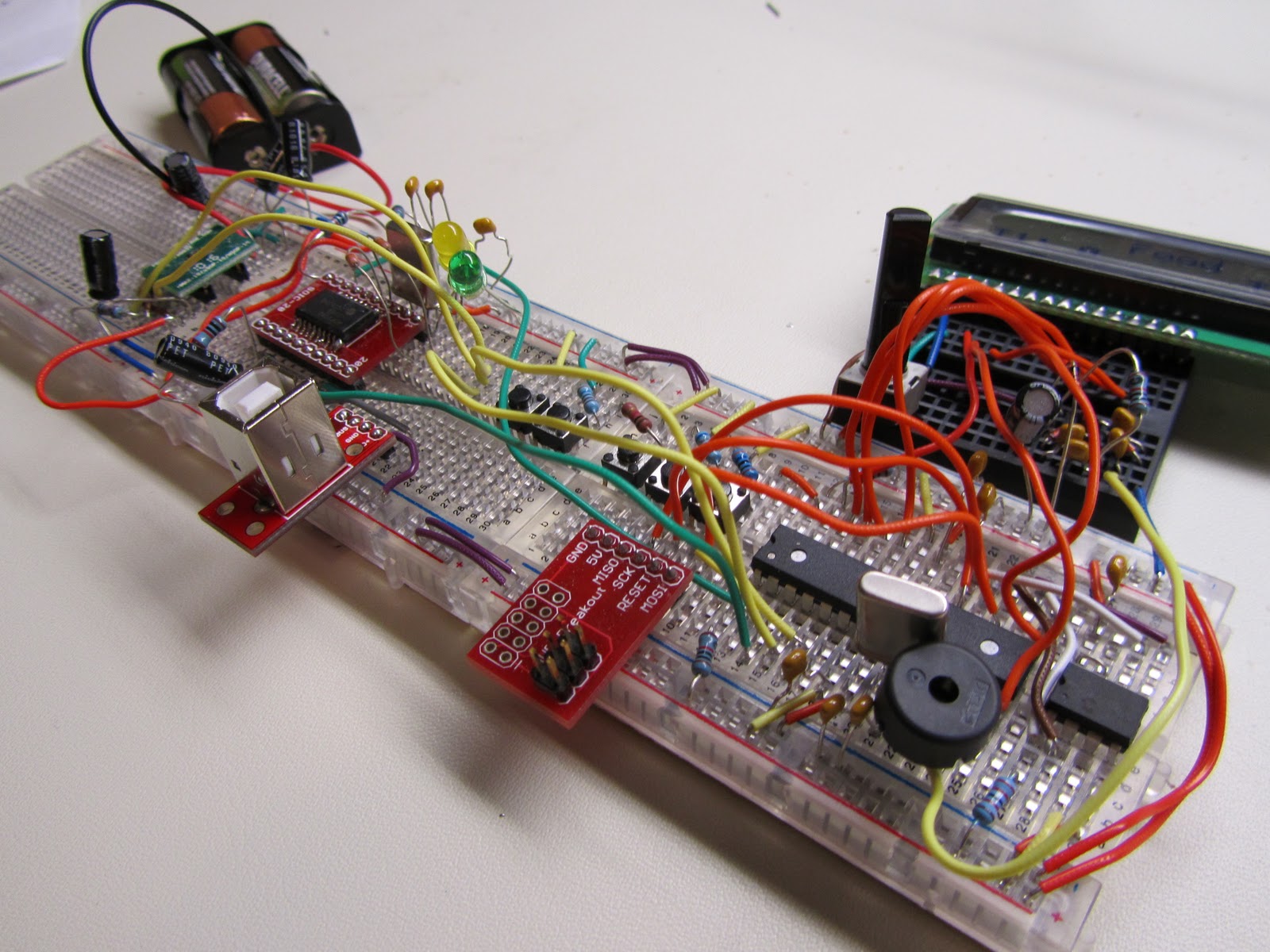
I have included some pictures of AVRphrase that you can use for reference if you want to build your own.

Configuration and Programming

Once you have assembled your AVRphrase, you will need to go through a few steps before it is ready to play.  The first is to program the Fuse bits on the microcontroller, and then program the firmware onto the microcontroller.  When you connect AVRphrase to your computer, you will need to install the USB Driver and use the Configuration Utility (found on the same page) to set the baud rate to 4800 and enable Tx/Rx LEDs.  Once this is complete, you can use the wordloader to upload a wordlist, and then your AVRphrase is ready to play.

You can contact me by commenting here or emailing me at zjonesengineering@gmail.com if you have questions, but the level of support I can provide is minimal.

Wednesday, January 5, 2011

AVRphrase


When I started playing around with embedded systems, I wanted to do something more interesting than just flashing an LED, and I spent a lot of time trying to come up with project ideas that would be useful (or at least fun) when they were done. One of the first ideas I had was to make my own version of catchphrase. Most of my extended family enjoys the game, but one problem with it is that some of the younger nephews can't understand most of the words. I thought it would be fun to create a version that they could play, and then the project grew from there.

 I made the first version right after getting an Arduino for Christmas 2009, so it was a fun project to get familiar with the Arduino and pretty easy to get up and running with the libraries and examples on the web. I spent about a week of evenings playing around before I got something I was happy with.  My first version was really simple, with all of the words stored in the AVR's flash using PROGMEM (I was able to fit around 700 words in 5 categories--any more words would give me problems, even though the flash wasn't even close to full). The problem with this was that the way I input the words was very, very tedious and was not something I could see any of my relatives understanding if I wanted to give it to them as something they could customize in the future.  The prototype was basically a 16x2 LCD, 5 push buttons, an ATmega328 mcu, a 16 MHz crystal, a piezo buzzer, and a 5V linear regulator.  I used a socket for the microcontroller so that I could pull it out and place it in my Arduino to program it.  I soldered it together on a protoboard, but didn't have a good enclosure or any power management.  It ran off of a 9V battery, and to turn it off you had to unplug the battery.  It was fun to work on, and a good proof-of-concept, but I got sidetracked for a while after I finished it.


I started thinking that it would be a fun project to take further.....maybe get a pcb printed and make enough to give as Christmas presents next year. Then I saw a post on Hackaday of someone who had done a similar project, but with a price tag over $200.  That was one of the things that made me decide I could definitely put this together, and for way less.  Christmas 2010 was the goal.  As I started thinking it through, I came up with more features that I could add, and other ways it could be used. The original used a 16x2 LCD display, and I would probably keep that on the next one. I also think the layout of a 5 pushbutton interface works well.  I had two buttons for keeping score, one for changing categories, one for starting/stopping the game, and one to advance to the next word.  It's a little different than the real Catchphrase, but the interface seems a little cleaner to me.  I definitely needed to add an on/off capability, as the last version was always on when the battery was connected. I also wanted  it to run off of a couple of AA batteries instead of a 9V.  The major change that I wanted to make was to remove the wordlist from the flash memory of the micro. By using an external EEPROM chip (SPI or I2C),  I could store the wordlist there and have a minimal code footprint on the micro. I could also add a mode where you could connect the microcontroller to a computer and use it as a UART to SPI bridge to program the wordlist into the EEPROM.  I needed USB capability if I wanted anyone else to be able to upload new word lists, as well as a simple way to upload new words.  With these ideas in mind, I set out to begin my design.

I decided right away that I wanted to move away from the Arduino development environment and switch to straight avr-gcc if I stuck with an AVR, or potentially use this as an opportunity to gain experience with another micro like PIC or MSP430.  The requirements I initially laid out for the microcontroller are listed below:
  • SPI/I2C - For interfacing with external EEPROM
  • UART/USB - For connecting to computer to program EEPROM
  • 5 GPIOs - Buttons
  • 7-11 GPIOs - LCD, Piezo buzzer 
  • 4-8 kB program space (rough estimate)
The list is pretty basic, and I knew that the ATmegaXX8 series would be up to the task and I already had a simple AVR ISP programmer, although at school I had access to a Dragon as well. I had a few PICs with built in USB that met the requirements, but I would be leaving college in a few months and thereby losing access to a PIC programmer. I also have a TI ez430 kit,  but I'm not sure that the series of 430 that comes with that kit would have worked.  In the end, I decided to stick with an AVR because of familiarity and the tools I already had, but I plan on using a different family of micro on my next project to try and expand my capabilities.  I had ATmega48, ATmega168, and ATmega328 chips in DIP packages, which were perfect for prototyping, and I could figure out how much code space I actually needed before actually selecting a chip because of the simplicity of switching between them.  I programmed the chips in AVR-GCC within AVR Studio.  I got pretty used to using the debugWire feature of the Dragon on school projects, and ended up picking one up after I graduated, which was very helpful for this project.

I had a pretty good idea in my head of what I wanted to do, so I started breadboarding another prototype.  I worked slowly and tried to get each functional piece working and simple "driver/interface" code written before moving on.  I pretty much always had the freeware CadSoft Eagle schematic editor up while I was working and kept the schematic consistent with what I had breadboarded.  The schematic definitely evolved as I went, but you can see the final version below.


At the top left of the schematic is the power regulator.  It's an MCP1259 inductorless charge pump DC-DC converter from Microchip that provides a regulated 3.3V from a 1.8-3.6V supply.  My V+ is coming from 2 AA batteries, and this chip also has a bypass feature that I'm using when I enter the power down state.  I used this chip, along with a couple others from Microchip because I was able to obtain some samples of them to test as a student and they worked well for my application. At the top middle is the LCD, which is a standard 16x2 character LCD.  I was able to find these pretty cheaply from  Xenon-Tech.  The LCD needs 5V power, so I stepped up the 3.3v using a voltage quadrupler and a 5.1V zener diode (see lower left of schematic) as described in this application note.  At the top right is an MCP2200 USB-UART converter, which is used to communicate with a PC to upload a new word list.  I used this instead of an FTDI232 chip because it was about half the price (although it did require an external 12 MHz crystal), but it doesn't work on Mac (or at least didn't at the time I was working with it), which is a downside.  At the bottom right is a chain of buttons configured as a voltage divider and connected to an ADC pin on the microcontroller.  This allowed me to use only one pin to read all 5 buttons, and I handled the debouncing in software.  At the bottom is the EEPROM chip.  I'm using a 25AA512 SPI EEPROM, which has 512Kbit and 1,000,000 erase/write cycles.  This series of memory chips goes all the way from 1Kbit to 1Mbit, and I'm using this one because it was a good balance of cost and storage.  Because my LCD is a 16 character display, I store each word/phrase as 16 characters regardless of the actual size, which simplified addressing and knowing where the words would be stored in memory, and allowed me to have ~4000 words/phrases.  I think the actual Hasbro Catcphrase has ~10,000 phrases, but 4000 is plenty for my homemade version, and it would be a simple change to move to the larger chip if I needed to.  I had a piezo buzzer and programming header, but pretty much everything else on the schematic is just supporting components.

I wanted my final design to be surface mount, and some of the chips I selected were only available in surface mount packages, so I had to use breakout boards for those in my prototype.  I got the breakout boards from Sparkfun and Proto-Advantage, and they were perfect for what I needed.  I kept my breadboarded prototype up to date even after I moved on to the PCB and was making minor adjustments there, just so I would always have an easy to modify prototype.  You can see the breadboarded version below.


Once I had the hardware finalized (or at least I thought it was finalized) and test code written for each portion, I decided it would be best to lay out a pcb and get the actual hardware in hand, as that was the longest lead time item, and I could worry about finalizing the software later.  I used Eagle to lay out the pcb, and had them fabricated through Gold Phoenix PCB using their 2 layer 155 sq. in. panel service, which I was very pleased with.  The physical constraints on my board came from the case I'd selected, and I was able to fit 15 boards on their panel.  The holes in the four corners are used to mount the board to the case.


Even though I had 15 pcb's, I hadn't really planned on making that many.  I bought enough components to populate 10 of them (10 was the cut-off for a price break on a lot of the components), thinking I'd make some mistakes and have 8 or 9 in the end (I ended up with 9 working units, and the one that's broken just needs an new MCP2200 chip and then it's good to go).  The "bottom side" of the pcb is actually the top of the game, but only has the screen and 5 buttons, which were all through-hole components.


The top of the pcb (bottom of the game) is where everything else is.  There were a couple of mistakes on the board, but I was able to fix them by hand.  At the bottom left is a pull-up resistor that was accidentally inline with the voltage divider-to-ADC path.  Luckily, it was over a 3.3v pour, and I was able to scrape away a small patch of solder mask and make a new "pad" for the resistor and jumper the old pad with solder.  The other mistake came from not reading the datasheet for my USB-UART converter closely enough.  It has a pin called Vusb, which I thought needed to be connected to the 5V USB pin.  It actually has it's own internal regulator, and I just needed a capacitor there.  I was able to cut the trace and add the capacitor after the fact.  Another mistake I didn't fix was that I forgot to connect a GPIO from the mcu to the reset pin on the USB-UART converter.  This is a pain, because sometimes the chip gets messed up and needs to be reset, but I have to do that by disconnecting the batteries rather than in software.  Otherwise, I was very pleased with how it turned out.


Once I had the hardware complete, I moved on to finishing the software.  I'd written most of the functions I needed already, I just had to write my main routine and make any fixes that came up.  When the mcu initializes, it checks the first page of EEPROM, which lets it know how many categories there are, and then reads in the name and starting/stopping memory locations for that category.  It only stores this information for the current category, and has to go back and read out the information for the next category when you change categories.  I have a few timers running, but the main process occurs once every 50 ms.  This is where button presses are registered and actions are taken.  The duration of the game round is randomly selected to be between 45 and 75 seconds at the beginning of each round.  Random words are selected by taking the value of a 16 bit timer at the time of the button press modulus by the size of the current category.  The timer gets progressively faster as the round goes on, and lets out a long beep to signal the end of the round.  In between rounds, the players can add points to either team, and the game will announce when a team has won.  After three minutes without any button presses, the game enters a power-down sleep mode and sets up a pin change interrupt on the ADC pin connected to the buttons.  Pressing any of the buttons (except for team 2 score) will wake up the device and re-initialize everything.  I ended up using the ATmega48, and when I was done it was 99.7% full on program space, which limited me from implementing a few other features I'd thought up later, but I still got the basic functionality in there.

The PC software to load words is written in Processing.  I tried to make it as simple as possible so that the user just has to click "play" and everything works once their lists are set up.  I have a data folder set up where the user adds all of their category names to a file called "CategoryNames.txt".  They then have to create a text file with the same name and fill it with their word list.  The processing sketch would run on Windows, Linux, or Mac, but the USB-UART chip doesn't support Mac, and I'm the only one I know who uses Linux, so I just gave everyone directions for Windows.  There's some simple error checking that takes care of common problems, but I fully expect to have to do some more troubleshooting once others start using it.  I gave everyone a CD with a user manual, USB drivers, sample word lists, and the wordloader program, so they should have everything they need to customize their AVRphrase.  The default category list was ~2800 words, which left them with plenty of room to add more, and they can always remove the defaults.

I cut the cases using a Dremel drill press, and they're pretty rough, but they work.  The last few I did definitely look better than the first couple.

The game plays pretty much exactly the same as the original Catchphrase, and is a lot of fun for groups of 4-10 people.  The fact that you can create custom categories also adds another fun element (my nephews love the Star Wars category).  I also think it has value as an educational tool, and could be marketed to teachers as something they could put their vocabulary words on and have students play for a fun learning/review game.  Below you can see a brief video of how the game works.  The end product ended up costing ~$30 each.  There are a few things I would have done differently if I were to do this again, but I had a lot of fun with the project and was able to get it finished up by Christmas Eve.